


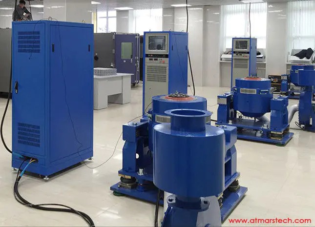
Vibration Testing: The Engineering Reality Behind Product Reliability
Why Vibration Failures Are Systematically Underestimated
Fatigue cracks caused by vibration are insidious. Unlike an overtemperature event that triggers immediate failure, vibration damage accumulates silently over millions of cycles. A microscopic crack at the base of a through-hole component lead may grow for 10,000 km of road transport before it finally opens under a single pothole impact — an event that looks like random bad luck but is entirely predictable with proper vibration testing.
Three structural reasons explain why vibration failures are underestimated in product development:
- Resonance masking: A product that performs perfectly on the bench may amplify road or operating vibration by a factor of 5–20× when its natural frequency aligns with an excitation frequency. This resonance condition cannot be found without a swept-sine or random vibration sweep.
- Multi-axis independence: Vertical vibration test results do not predict horizontal or lateral failure modes. Many connector unlatch events occur only under cross-axis excitation.
- Combined environment blindspot: Elevated temperature reduces material damping and changes stiffness. A component that passes vibration at 25°C may fail at 85°C under identical acceleration levels, yet the two tests are often conducted separately.
The Physics Behind the Test: Frequency, Acceleration, and PSD
Understanding the three core parameters of vibration testing allows engineers to design test profiles that genuinely replicate service conditions rather than simply meeting a bureaucratic checklist.
Frequency range (Hz): Most structural resonances in electronic assemblies fall between 10 Hz and 2,000 Hz. Vehicle powertrains generate dominant content from 5 Hz to 500 Hz, while aircraft fuselage vibration extends toward 2,000 Hz. High-frequency ultrasonic content above 2,000 Hz rarely causes structural fatigue but can affect MEMS sensors and acoustic components.
Acceleration (g, peak or RMS): The force applied to a mass equals mass × acceleration. At 10g peak acceleration, a 100 g component experiences a 1 N dynamic force — sufficient to fatigue many fine-pitch PCB joints within hours of continuous vibration at resonance. Automotive underhood components routinely experience 30–50g shock pulses during rough-road events.
Power Spectral Density (PSD, g²/Hz): Random vibration is described not by a single amplitude but by an energy spectrum. A PSD profile defines how much acceleration power exists at each frequency. The overall g RMS value is the square root of the area under the PSD curve. Matching the PSD profile of the test to the field environment is what separates predictive testing from arbitrary punishment.
| Test Type | Signal Profile | Primary Use Case | Key Standard |
|---|---|---|---|
| Swept-Sine | Single frequency, swept slowly across range | Resonance search, fatigue at known frequency | IEC 60068-2-6 |
| Random Vibration | Broadband noise with defined PSD | Road transport, aerospace turbulence simulation | IEC 60068-2-64, MIL-STD-810H |
| Shock | Half-sine or trapezoidal pulse | Drop events, road bumps, pyrotechnic separation | IEC 60068-2-27, MIL-STD-810H |
| Combined (Temp + Vib) | Random or swept-sine inside thermal chamber | HALT, HASS, aerospace electronics | RTCA DO-160, IEC 60068-2-53 |
| Resonance Dwell | Fixed frequency at identified resonance | Accelerated fatigue life testing | IEC 60068-2-6, ASTM E1049 |
Vibration Testing Standards: What the Industry Actually Requires
Compliance-driven vibration testing is not monolithic — each sector has developed its own test profiles shaped by actual field data. Engineers selecting a test specification must match the standard to the deployment environment, not simply choose the most demanding profile available.
- IEC 60068-2-6 / -27 / -64: The baseline family for general electronic and electromechanical products. Part 2-6 covers sinusoidal vibration, Part 2-27 shock, and Part 2-64 random vibration with defined PSD tables for road, rail, and airborne environments. Referenced by virtually every global product standard.
- MIL-STD-810H: The US Department of Defense environmental method. Method 514.8 (vibration) and Method 516.8 (shock) include tailoring guidance that requires test engineers to derive PSD profiles from measured field data rather than using generic tables — a significantly higher engineering burden but a far more accurate result.
- IATF 16949 / ISO 16750-3: For automotive components, ISO 16750-3 defines vibration profiles based on mounting location: powertrain-mounted parts face acceleration levels 4–8× higher than body-mounted electronics. Misidentifying mounting location is one of the most common root causes of automotive field vibration failures.
- UN38.3 (Section T.3): The mandatory transport safety test for lithium batteries shipped by air, sea, or road. The vibration profile (7 Hz to 200 Hz, 2g peak, 15 minutes per axis) simulates worst-case transport vibration for packaged cells and battery pack systems.
- RTCA DO-160G Section 8: The avionic standard for airborne equipment. Its random vibration PSD levels are among the most demanding in commercial industry, reflecting high-altitude turbulence and engine-induced structural excitation.
- IEC 62133 / GB 31241: Consumer lithium battery standards. The vibration clause requires cells and packs to survive 90-minute random vibration per axis without leakage, fire, or rupture.
Five Industries Where Vibration Testing Defines Product Fate
While vibration testing applies across manufacturing sectors, five industries treat it as an absolute gate, not a best-practice recommendation.
1. Electric Vehicle (EV) Battery Packs
A battery pack in an EV is simultaneously a structural member, a high-voltage electrical enclosure, and a source of continuous vibration from road inputs and electric motor harmonics. The battery pack vibration testing machine must replicate 10-year service life road spectra in compressed time. Failure modes include: busbar joint cracking, BMS connector intermittency, coolant fitting fatigue, and cell-to-module bonding delamination. All are silent killers — they do not manifest until the pack has already been deployed in tens of thousands of vehicles.
2. Consumer Electronics and 3C Products
Smartphones, tablets, and laptops experience thousands of micro-drop and handling vibration events per year. The dominant failure mode is solder joint fatigue at BGA packages, where the thermal mismatch between silicon die and PCB substrate creates a pre-stressed interface that vibration progressively opens. The 3C vibration testing system — designed specifically for compact consumer devices — uses high-frequency electromagnetic exciters to compress years of handling events into hours of structured testing.
3. Aerospace and Defense
No sector has zero tolerance for vibration-induced failure more rigorously enforced. Avionics must survive rocket launch loads (up to 100g broadband), continuous aircraft structural vibration, and landing shock simultaneously. Military-grade vibration shakers certified to MIL-STD-810H specifications are required. Fixture design is as critical as the shaker itself — a poorly designed fixture introduces spurious resonances that can either mask real weaknesses or create false failures.
4. Industrial and Transportation Packaging
Products that survive factory testing can be destroyed in transit. ASTM D4169 and ISTA 2A define stacked transport vibration profiles for road freight. High-frequency vibration shakers simulating truck-trailer resonance (typically 1–3 Hz for the trailer suspension and 10–30 Hz for cargo resonance) are used to validate packaging design before launch. The carton transport simulation vibration shaker handles toys, electronics, and furniture packaging across these frequency ranges.
5. Medical Devices
IEC 60601-1 and ISO 13485 require vibration testing for medical devices that are transported or used in mobile environments. Infusion pumps, portable diagnostics, and surgical robots must maintain calibration and structural integrity after transport vibration. For implantable devices, internal resonance of micro-components is a patient-safety concern that requires characterization with laser Doppler vibrometry before any accelerated test is designed.
Selecting the Right Vibration Test System: Five Engineering Criteria
Not all vibration shakers are equivalent. Engineers specifying test equipment for a new laboratory or expanding an existing facility should evaluate five criteria before committing to a platform:
1. Force Rating (kN) vs. Test Mass
The rated force of an electromagnetic shaker defines the maximum product of DUT mass × peak acceleration. A 5 kN shaker running at 20g can test a DUT mass of up to 25 kg. Engineers frequently undersize shakers by forgetting to include fixture mass in the calculation — a 15 kg aluminum fixture leaves only 10 kg of payload capacity on a 5 kN / 20g system. The air-cooling vibration analysis equipment spanning 100 to 6,000 kg effective mass covers the full range from component-level to system-level testing.
2. Frequency Range and Uniformity
The usable frequency range is not simply 5–3,000 Hz as stated in a datasheet. It is the frequency range over which the table surface acceleration uniformity remains within ±3 dB across the full load range. Poorly designed armatures develop internal resonances that corrupt test data at specific frequencies. Independent verification of uniformity with a loaded table at rated force should be requested before purchase.
3. Slip Table and Multi-Axis Capability
Vertical-axis testing alone is insufficient for most applications. A horizontal slip table allows in-plane vibration without requiring a second shaker. The multi-axis high-frequency vibration shaker with X/Y/Z flexible suspension eliminates repositioning time and reduces total test duration by up to 60% compared to three separate single-axis test campaigns.
4. Cooling Method: Air vs. Water
Air-cooled shakers are simpler to install and maintain but are limited in duty cycle at maximum force. The water-cooled vibration testing system supports continuous operation at rated force without thermal derating — essential for 24-hour accelerated life tests where any reduction in force level invalidates the fatigue equivalence calculation.
5. Controller Software and Data Acquisition Integration
Modern vibration controllers must support closed-loop random vibration control, resonance tracking, time-history replication, and real-time Fast Fourier Transform (FFT) analysis. Open APIs for integration with external DAQ systems and laboratory information management systems (LIMS) are increasingly required by automotive OEM customers. Verify that the controller software exports standard formats (UFF58, CSV, HDF5) compatible with the customer's post-processing environment.
Combined Vibration and Environmental Testing: The Next Frontier
Products rarely experience vibration in isolation. Real-world environments couple mechanical excitation with temperature extremes, humidity, and in some cases altitude. The three-combination environmental test chamber — integrating vibration, temperature, and humidity into a single test sequence — is becoming the standard for automotive Tier-1 suppliers, aerospace subcontractors, and battery cell manufacturers.
The technical challenge of combined testing lies in two areas:
- Thermal influence on vibration response: Material elastic modulus, damping coefficient, and adhesive bond strength all vary with temperature. A proper combined test profile accounts for how resonant frequencies shift as the DUT cools from +85°C to -40°C during a thermal cycling sequence while simultaneously under 5 g RMS random vibration.
- Fixture thermal expansion: Differential thermal expansion between the aluminum fixture and the steel shaker armature introduces time-varying preloads on fasteners that can influence test results. Fixture material selection and preload specifications must be part of the test plan, not afterthoughts.
For EV battery pack validation programs, combining the UN38.3 T.3 vibration profile with the IEC 62133 thermal cycling sequence in a single step-in three-comprehensive testing chamber can reduce total qualification time by 35–50% compared to sequential single-discipline testing.
Common Mistakes in Vibration Test Program Design
Laboratory experience across automotive, aerospace, and consumer electronics programs consistently reveals the same recurring errors:
- Using field worst-case data directly as the test profile: Field measurement data contains single rare events that should be treated statistically, not converted directly into a 30-minute test profile. Over-testing relative to field reality produces products that are expensive to build and still do not target the actual field failure mechanism.
- Ignoring fixture first-resonance frequency: A fixture whose first resonance falls within the test frequency range distorts the drive and response relationship, making closed-loop control unstable and test results unrepeatable. Fixture first resonance should be at least 2× above the highest test frequency.
- Single control accelerometer placement: Controlling vibration from a single table center point creates up to 40% force non-uniformity at corners for large or asymmetric DUTs. Average control strategies using multiple accelerometers at fixture attachment points provide better spatial control fidelity.
- Skipping pre- and post-test functional verification: Vibration tests that end with only a visual inspection miss intermittent failures that only manifest under electrical operation. Full functional test at the end of each axis is mandatory in MIL-STD-810H and should be standard practice in all programs.
Mentek's Vibration Testing Portfolio: From Component to System Level
Mentek's vibration testing equipment covers the full range of force classes, frequency ranges, and application requirements that modern reliability programs demand. The product line is organized into three tiers:
Compact Lab Series (L-Series): The compact lab vibration test table and L-Series vibration testing system target small components and 3C consumer electronics. Force ratings from 50 N to 1,000 N cover frequencies up to 3,000 Hz, meeting IEC 60068-2-6, IEC 62133, and UN38.3 T.3 profiles.
Medium Industrial Series (M-Series): The M-Series 3C vibration testing system and multi-ton electromagnetic shakers handle automotive subassemblies, industrial controls, and medium-format battery modules. Horizontal slip tables are available as standard configurations, enabling X/Y-axis testing without fixture rebuild.
High-Force Water-Cooled Series: The water-cooled vibration testing system with onsite installation support and the military-specification high-frequency vibration shaker address full vehicle subsystems, defense hardware, and large aerospace structures. These systems include onsite commissioning, operator training, and calibration certification to meet customer IATF 16949 and AS9100 quality system requirements.
All systems support integration with the HE-Series expansion table fixture, allowing customers to increase effective test area without replacing the core shaker platform — a significant total cost of ownership advantage for laboratories whose DUT dimensions evolve over time.
|
Ready to Build a Vibration Testing Program That Actually Reflects Your Field Environment? View Vibration Test Equipment Request a Free Technical Consultation |